2015年12月7日星期一

Comparison Between EPON and GPON

PON is the abbreviation of passive optical network, which only uses fiber and passive components like splitters and combiners. EPON (Ethernet PON) and GPON (Gigabit PON) are the most important versions of passive optical networks, widely used for Internet access, voice over Internet protocol (VoIP), and digital TV delivery in metropolitan areas. Today we are going to talk about the differences between them.
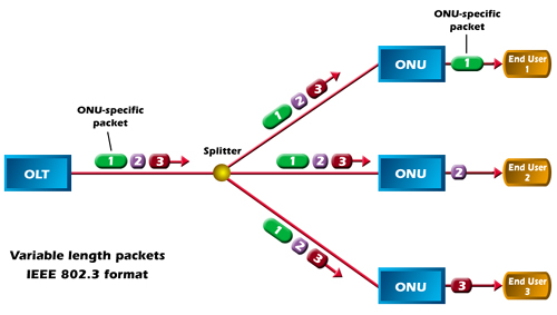
PON network
Technology Comparison
EPON is based on the Ethernet standard 802.3 that can support the speed of 1.25 Gbit/s in both the downstream and upstream directions. It is well-known as the solution for the "first mile" optical access network. While GPON, based on Gigabit technology, is designated as ITU-T G.983 which can provide for 622 Mbit/s downstream and 155 Mbit/s upstream. GPON is an important approach to enable full service access network. Its requirements were set force by the Full Service Access Network (FASN) group, which was later adopted by ITU-T as the G.984.x standards–an addition to ITU-T recommendation, G.983, which details broadband PON (BPON).
As the parts of PON, they have something in common. For example, they both can be accepted as international standards, cover the same network topology methods and FTTx applications, and use WDM (wavelength-division multiplexing) with the same optical frequencies as each other with a third party wavelength; and provide triple-play, Internet Protocol TV (IPTV) and cable TV (CATV) video services.
Costs Comparison
No matter in a GPON or in an EPON, the optical line terminal (OLT), optical network unit (ONU) and optical distribution network (ODN) are the indispensable parts, which are the decisive factor of the costs of GPON and EPON deployments.
The cost of OLT and ONT is influenced by the ASIC (application specific integrated circuit) and optic module. Recently, the chipsets of GPON are mostly based on FPGA (field-programmable gate array), which is more expensive than the EPON MAC layer ASIC. On the other hand, the optic module’s price of GPON is also higher than EPON’s. When GPON reaches deployment stage, the estimated cost of a GPON OLT is 1.5 to 2 times higher than an EPON OLT, and the estimated cost of a GPON ONT will be 1.2 to 1.5 times higher than an EPON ONT.
We all know that the ODN is made up of fiber cable, cabinet, optical splitter, connector, and etc. In the case of transmitting signals to the same number of users, the cost of EPON and GPON would be the same.
Summary
Nowadays, since many experts have different opinions on GPON and EPON. Thus, there is no absolute answer to determine which is better. But one thing is clear: PON, which possesses the low cost of passive components, has made great strides driven by the growing demand for faster Internet service and more video. Also, fiber deployments will continue expanding at the expense of copper, as consumer demands for "triple-play" (video, voice and data) grow.
Originally published at http://www.chinacablesbuy.com/comparison-between-epon-and-gpon.html
2015年12月1日星期二

https://www.linkedin.com/pulse/splice-connector-which-choose-ftth-drop-cable-installation-iris-xu?published=t

To choose a right drop cable interconnection solution for FTTH network is very importance. Connectors and splice, as the two common ways to interconnect drop cables, are widely used at FTTH deployment. We all know that the splice can offer a permanent joint, while the connector can be easily operated by hand. But there is a proverb that says you can’t have your cake and eat it too, the providers have to choose between the two. So which should we choose? This paper is going to discuss them in details via talking about their own advantages and disadvantages.
Pros and Cons of Splice
Let’s first go with the splice. Splice is capable of great reliability and can provide excellent optical performance, so that it has been praised highly for many years. What is more, when the connector is not mated, splicing can protect the connector end-face from contaminants that can cause high optical loss or even permanently damage the connector. It just reduces these damages to a minimum. Another advantage of the splice is that it enables a transition from 250 µm drop cable fiber to jacketed cable.
And then let’s talk about its disadvantages. The main drawback of it is the lack of operational flexibility. For example, if you want to reconfigure a drop cable at the distribution point, you should remove one splice, rearrange fibers and splice two new fibers. This requires the technician to carry special splicing equipment for simple subscriber changes. And also, when you are in the process of splicing at the distribution point, you should be careful with the fiber in case of bending or breaking it. If a splice is used at an ONT, there must be space for a tray to hold and protect the splice. This increases the ONT size and potentially the cost.
Pros and Cons of Connector
Unlike splice, connector can provide great operational flexibility in that they can be mated and unmated repeatedly, allowing them to be reused over and over again. When you need to connect a drop cable, you can used the connector to mate without any tools.
Also, connector has its own disadvantages, just as every coin has two sides. The biggest problem of it is the material cost. Therefore, providers must weigh the material cost of connectors along with the potential for contamination and damage against their greater flexibility and lower network management expense.
Conclusion
From the above analysis, now we can draw a conclusion. Splice is more suitable for no fiber rearrangement circumstances, such as greenfield or new construction application. While connector can offer flexibility both at the curb and at the home since it can be plugged and unplugged multiple times.
In a word, drop cable interconnect solution plays an so important part in FTTH network that you should be very careful when you choose the way to do the connection. The right choice will help you to save costs and operate more efficiently. But whether you need a splicer or connector, you can always find it in Fiberstore. For more information, visit FS.COM.
Originally published at http://www.chinacablesbuy.com/splice-or-connector-which-to-choose-for-ftth-drop-cable-installation.html

2015年11月24日星期二

FTTH: Bringing You the Life-enhancing Benefits

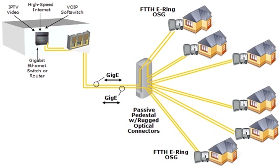
FTTH, which is short for fiber to the home, is an ideal fiber optic architecture as the fiber optic service to home. It can transport large amount of data from caller to caller fast and reliable. In the light of present situation, there are more than 10 million homes all over the world adopted FTTH network in that it holds many advantages over current technologies. Here let us figure them out.
FTTH_architecture
Benefits of FTTH
Some experts has pointed that fiber-to-the-home connections are the only technology with enough bandwidth to handle projected consumer demands during the next decade reliably and cost effectively. Of course, we all know that FTTH is a passive network that do not need active components. This feature makes it dramatically minimize the network maintenance cost and requirements. What is more, it features local battery backup and low-power consumption, which indeed bring much convenience to people’s lives. But, are that all its advantages? I am afraid that these simple advantages can’t convince people that FTTH can bring the life-enhancing benefits to their lives. And so do you. So, what are its remarkable benefits? Please take a look at the blow words.
The first thing you should know that it is less susceptible to corrosion or power surges from lightning and other sources, resulting in greater reliability. Because of its higher stability and less interruptions, it replaces copper infrastructure with new technology, allowing for future evolution of technology.
Second, it can provide virtually unlimited bandwidth capacity. As we mentioned above, it can support large amounts of data and keep up with consumer and technology demands, which makes it access to more advanced communication products like streaming video, internet TV, quality video conferencing, “smart home” technology, IP video home monitoring, gaming and so on.
Third, it brings profits to your home and the community. According to the Fiber-to-the-Home Council, we have got a amazing data that FTTH has increased the home value as much as $5,000. With the advanced technology, it made the “global village” come true. Even at ultra-rural areas, people still can compete on a global scale in their work or business.
Two Factors You should know before deploying FTTH
Now that we have learned the benefits of FTTH, I guess some people may intend to deploy FTTH network. Fiber deployment is a trade-off driven by the cost of the service relative to the potential revenue per subscriber. So before you deploy it, please read the below tips which can help you avoid loss.
Deploy the fibers in the high economic density of the service area. The number of houses and enterprises that a fiber passes by will be translated into the number of money. So , if you deploy your network in a high economic density place, you will get your investment back and make high profits soon.
Deploy your network in the place where has existed current fiber/copper wiring. It is easiest to serve a given area by following the current conduits and loops and staying with the rough topology of the old installation. This method will save you a lot of money compared with restarting wiring for your network. So if you can’t run the fiber directly to the home, just take it is to the node where the loops currently collect.
Conlusion
Recently, FTTH has been adopted by thousands of families, and the continuous prosperity will last for a long time. If you want to deploy a FTTH network, you can come to Fiberstore to get the needful tools. In Fibersotre, you can find the most cost-effective FTTH solutions including FTTH fiber cables, fiber optic splitters and some others. They are all tested in good condition with reasonable prices. So, if you choose Fiberstore, you just choose your better FTTH network with low cost.
Originally published at http://www.chinacablesbuy.com/ftth-bringing-you-the-life-enhancing-benefits.html

2015年11月16日星期一

Three Ways to Optimize Your Home Wireless Network

Nowadays, the home wireless network has grown significantly, which has brought a lot of convenience to people because of its fast and reliable features. But the world is not always perfect. When the signal keeps dropping or the speed is so slow, people might get frustrated. As a result, there has been a trend that people are more and more focusing on the speed of the network. This paper will give you some advice to optimize your home wireless network.
Organize Your Connected Devices
The easiest and most important way to optimize the home wireless network is to organize your connected devices in a structured media enclosure serve as the central hub. This enclosure can be the best housing for all of your devices, including routers, switches and modems, which can save you valuable space so that eliminate clutter and have easy access to all of your connected devices, all while maintaining a clean aesthetic. What is more, when you put your enclosure in the center of your home, your network connection coverage can be up to maximum. Remember that keep your access points off the floor, out of closets and cabinets, and away from walls and large metal objects, like file cabinets.
Check Your Network Devices
Check your network devices to make sure if they can still support the speed. You know, the technology is always advancing, so maybe it’s time to replace your old devices. For example, you can check the network adapter in your wireless devices such as computers or phones, to see if they use the 802.11n (wireless-N) protocol. If “Yes”, you can get the fastest speeds. But if your devices use the 802.11g protocol, it can be limited to wireless-G speeds (maximum 54 Mbps).
Also, you should know that the fewer devices on a wireless network, the faster the network is likely to run. So you can connect some of your equipment by a hardwired connection such as CAT cabling.
Change Channel Width
In order to adapt to the further advanced wireless protocols, one of the ways to increase the speed is using wider wireless channels. In general, if you want to achieve maximum speed, the routers should use a 40Mhz channel width. But the fact is that most routers come with 20MHz as the default width, which is in an attempt to avoid interference. This situation may be a potential negative affect on some users. If you start to notice issues, switch back to a 20Mhz operation. Also note that this isn’t really for increasing how fast you browse the internet. This change is more likely to be evident when streaming/transferring files between devices on your network. For this case, you can just find the “Channel Width” setting in your router’s setting and change it to “Auto 20/40MHz”.
Conclusion
After reading the above steps, it would be of some help to build your home wireless network. If you do check your devices or want to do some hardwired connections, you could visit FS.COM for help. It can offer the CAT cables and other telecommunication equipment with good quality and reasonable price, and you can pick up what you want. For more information, visit FS.COM.
Originally published at http://www.chinacablesbuy.com/three-ways-to-optimize-your-home-wireless-network.html

2015年11月9日星期一

How to Lower Cabling Temperature for PoE?

Popular speaking, PoE (Power over Ethernet) is a technology that lets network cables carry electrical power. Recently, PoE has made great strides because it has shown its great advantages such as saving time and cost, flexibility and reliability. As a result, cabling for PoE is at the explosive growth rates. But there is a problem in the cabling when power is added to balanced twisted-pair cabling. The copper conductors generate heat and temperatures could rise, which may lead to higher insertion loss and in turn shorter permissible cable lengths. So, how to lower cabling temperature for PoE? Here are some advice below.
Reduce the number of cables per bundle - If the cable bundle is too big or tight, the temperature will be higher. TIA (Telecommunications Industry Association), has done an experiment about whether the number of cables can influence the temperature. First, they tested the temperature of a bundle of 91 cables, and then they equally separated this cable bundle into three bundles and tested the temperature of each bundle. The results showed that the temperature of the 91 cable bundle is much higher than the smaller three cable bundles. In order to keep the result precise and reliable, they divided the three bundles into smaller bundles, and the result turned out to be the same. So a conclusion can be reached: Separating large cable bundles into smaller bundles or avoiding tight bundles will minimize higher temperatures.
Use higher category cabling - Higher category-rated cable typically means larger gauge sizes, and as power currents increase, these larger conductors will perform better than smaller cable. There is a picture below which shows the different temperature of different category cables with the cable bundle size increased. From this picture, we can see that higher category-rated cable is capable of more stable performance as it can allow for larger bundle sizes under the maximum 15-degree temperature increase. The allowable bundle size was 52 cables for Cat 5e, 64 for Cat 6, 74 for Cat 6A, and a similar increase for Cat 8.
different temperature of different category cables with the cable bundle size increased
Install Shielded Cabling - There is a comparison between Unshielded Twisted Pair (UTP) and Foiled Unshielded Twisted Pair (F/UTP). The samples of cable were tested carrying a PoE+ current of 600 mA per pair over all 4 pairs at an ambient temperature of 60 degrees Celsius. Each cable type was coiled into a separate 90 meters length and terminated with jacks at both ends. They then applied the current while monitoring the temperature rise of the bundle. After testing, they found that UTP cable performed worst, as it required more than 9 meters of length to be removed before it returned a passing insertion loss result. While the F/UTP performed significantly better, for it can pass at less than 90 meters. The difference between the performance lies in that UTP cable has no shield or isolation wrap barrier between the insulated conductors and the outer cable jacket material. In turn, there may be an interaction that changes the dielectric constant around the conductor and contributes to greater attenuation at higher temperature.
In a word, lower cabling temperature for PoE can be benefit to reach a high quality connectivity that is a crucial part in a flexibility and reliability network. The advice introduced above will help you lower cabling temperature for PoE. In addition, Fiberstore, one of the most famous telecommunication equipment manufacturers in the world, has devoted itself to deliver the products of highest performance for cabling systems and offer the best assemblies for fiber optic connectivity, which can help you to receive maximum return on infrastructure investment.
Originally published at http://www.chinacablesbuy.com/how-to-lower-cabling-temperature-for-poe.html

2015年11月3日星期二

UTP Cables Selection Guide

Since the copper cable is capable of the advantages, such as less expensive electronics and flexibility, the fiber optic cable can’t just replace it. As a result, while the consumer electronics keep going increasingly wireless, many LANs still rely heavily on copper cables to handle all the heavy lifting when it comes to transmitting data. For example, if you want to plug your computer into a broadband Internet connection, you just need a cable to complete this connection. This paper will introduce some common categories of copper cable used in today’s networks.
Category 3
The CAT3 cable is an UTP (unshielded twisted pair) cable whose data transmission rate is at the speed of 10Mbps. It is one of the oldest copper cable, and was used on a large scale in the early 90’s when it was the industry standard for computer networks. Of course, it is still used today for wiring offices and homes. Although it is still used in two-line phone configurations, it is no longer the the darling of the times when deploy the networks due to the advent of the Category 5 cable.
Category 5
As the successor of the CAT3 cable, CAT5 cable is capable of superior performance. Compared with CAT3 cable, CAT5 cable is the same with it in the structure--UTP, but has higher transfer rate, up to 100Mbps. The fact is that the speed of 100Mbps is also called Fast Ethernet, so the CAT5 cable has become the first Fast Ethernet-capable cable. But Now, it has been replaced by the CAT5e cable.
Category 5e
The CAT5e standard is an enhanced version of CAT5 cable, which is optimized to reduce crosstalk, or the unwanted transmission of signals between data channels. Similar to CAT 5 in appearance, CAT5e introduces some new wrinkles in the equation. For one thing, CAT5e uses four pairs of copper wire rather than the two that CAT5 relies on. The excellent capacity, that the speed of it can be up to 1000Mbps and the bandwidth can be up to 100 MHz, makes it become the one of the most popularized cable in today’s market. That is also the reason why it can replace the CAT5 cable.
Category 6
Supporting frequencies of up to 250 MHz and the 10BASE-T, 100BASE-TX, 1000BASE-T, and 10GBASE-T standards, it can handle up to 10 Gbps in terms of throughput. Some CAT6 cables are available in STP (Shielded Twisted Pair) forms or UTP forms. Compared with CAT5e cable, it has better insulation and thinner wires which can provide a higher signal-to-noise ratio, and is better suited for environments in which there may be higher electromagnetic interference. However, when deploying a network, the cost of CAT5e cable is much cheaper than CAT6 cable.
Category 6a
CAT6a’s data transmission rate is up to 10,000 Mbps and the maximum bandwidth is 500 MHz. Since it is in the form of STP, a specialized connector is usually needed to ground the cable. When you’re wiring up your home or office for Ethernet for the long haul, CAT6a is the perfect choice in terms of future-proofing.
Category 7
CAT7 cable, also known as Class F, is a fully shielded cable that supports speeds of up to 10 Gbps (10,000 Mbps) and bandwidths of up to 600 Mhz. It consists of a SSTP (screened, shielded twisted pair) of wires, and the layers of insulation and shielding contained within them are even more extensive than that of CAT6 cables. Because of this shielding, It is thicker, more bulky, and more difficult to bend. Additionally, each of the shielding layers must be grounded, or else performance may be reduced to the point that there will be no improvement over CAT6, even worse than CAT5. For this reason, it’s very important to understand the type of connectors at the ends of a CAT7 cable.
Conclusion
When you need a cable to attach your computer to the modem in your home or your office, you can choose the right cable after reading this guide. There are three factors that you should take into consideration: price, the quality of the cables and the kinds of device you have to connect. Fiberstore can offer the most cost-effective solution for your copper cabling, such as CAT3 cable, CAT5e cable and so on. Besides, the price and the quality of these cables are extremely attractive. Wanna buy? Just visit FS.COM.
Originally published at http://www.chinacablesbuy.com/utp-cables-selection-guide.html

2015年10月26日星期一

Differences Between FBT Splitter and PLC Splitter

Nowadays, with the further popularization of the optical fiber communication, fiber optic splitter plays an increasing significant role in many of today’s optical network topologies. Although there are variations of splitter types, the two most commonly deployed splitters are FBT (Fused Biconical Taper) splitter and PLC (Planar Lightwave Circuit) splitter. So, when you deploy your network, what kind of splitter you should choose may be a problem for you. And in order to solve this problem, this paper will give you a detailed introduction of differences between FBT splitter and PLC splitter.
Definition of FBT Splitter and PLC Splitter
Before you get to know the features of them, first you should know what them are. Next, each splitter will be introduced.
FBT Splitter - FBT is a traditional technology that two fibers are typically twisted and fused together while the assembly is being elongated and tapered. The fused fibers are protected by a glass substrate and then protected by a stainless steel tube, typically 3mm diameter by 54mm long. FBT splitters are widely accepted and used in passive optical networks, especially for instances where the split configuration is not more than 1x4. The slight drawback of this technology is when larger split configurations such as 1x16, 1x32 and 1x64 are needed.
PLC splitter - A PLC splitter is a micro-optical component based on planar lightwave circuit technology and provides a low cost light distribution solution with small form factor and high reliability. It is manufactured using silica glass waveguide circuits that are aligned with a V-groove fiber array chip that uses ribbon fiber. Once everything is aligned and bonded, it is then packaged inside a miniature housing. PLC Splitter has high quality performance, such as low insertion loss, low PDL (Polarization Dependent Loss), high return loss and excellent uniformity over a wide wavelength range from 1260 nm to 1620 nm and have an operating temperature -40°C to +85°C.
Feature Comparison of FBT Splitter and PLC Splitter
In the past few years, splitter technology has made a huge step forward, especially the PLC splitter technology. This situation resulted in that PLC splitter has become a higher reliable type of device compared to the traditional FBT splitter. Although being similar in size and appearance, the internally technologies behind these types vary, thus giving service providers a possibility to choose a more appropriate solution.
Operating Wavelength - As is mentioned above, PLC splitter can provide a range of operating wavelength from 1260 nm to 1620 nm. But FBT splitters only support three wavelengths (850/1310/1550 nm) which makes these devices unable to operate on other wavelengths.
Operating Temperature - Commonly, FTB splitter is to a high extent temperature sensitive, providing a stable working range of -5 °C to 75 °C. While PLC splitter operates at wider temperature range (-40 °C to 85 °C), allowing its deploying in the areas of extreme climate.
Split Ratio - The split ratio of FBT splitter is 1:8 and it can be higher with higher failure rate. The split ratio of PLC splitter can go up to 64, which is equal to all branches, thus providing a high reliability.
Cost - FBT splitter is made out of materials that are easily available, for example steel, fiber, hot dorm and others. All of these materials are low-price, which determines the low cost of the device itself. PLC splitter manufacturing technology is more complex. It uses semiconductor technology (lithography, etching, developer technology) production, hence it is more difficult to manufacture. Therefore, the price of this device is higher.
FBT and PLC splitter feature comparison
Conclusion
In a word, Compared with FBT splitter, the capacity of PLC splitter is better, but costlier than the FBT splitter in the smaller ratios. You can choose it according to your requirements. Fiberstore offers both FBT splitter and PLC splitter with good quality and low price. Whether in FTTx systems or in traditional optic network, Fiberstore splitter can help you to maximize the functionality of optical network circuits.
Originally published at http://www.chinacablesbuy.com/differences-between-fbt-splitter-and-plc-splitter.html

2015年10月21日星期三

MPO/MTP Solutions for High Density Applications

As the bandwidth demands grow rapidly, data centers have to achieve ultra-high density in cabling to accommodate all connections. MPO/MTP technology with multi-fiber connectors offers ideal conditions for high-performance data networks in data centers. This article will introduce information about MPO/MTP solutions, such as MPO/MTP trunk cable, MPO/MTP harness cable and MPO/MTP cassettes.
MTP/MPO Trunk Cable
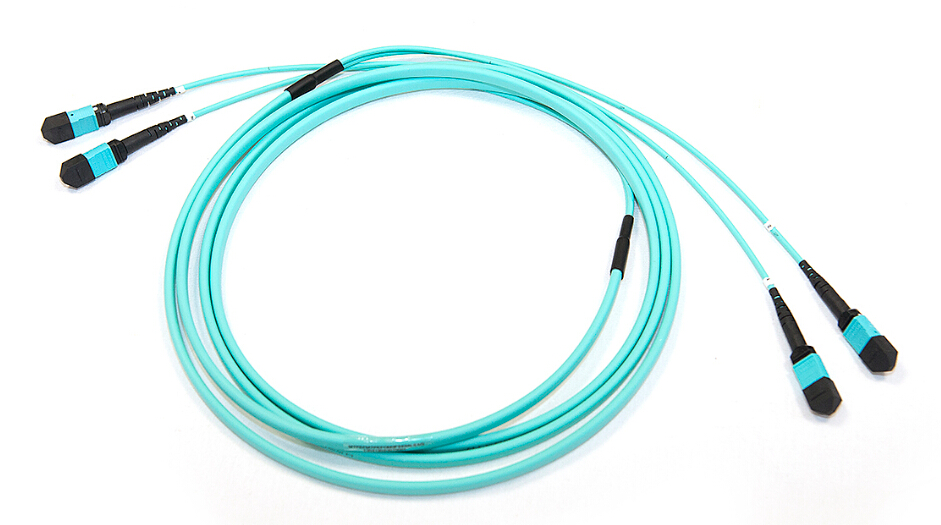
MTP/MPO trunk cables are terminated with the MTP/MPO connectors (as shown in the following figure). Trunk cables are available with 12, 24, 48 and 72 fibers. MTP/MPO trunk cables are designed for data center applications. The plug and play solutions uses micro core cable to maximize bend radius and minimize cable weight and size. Besides, MTP/MPO trunk cables also have the following advantages:
  • Saving installation time–With the special plug and play design, MTP/MPO trunk cables can be incorporated and immediately plugged in. It greatly helps reduce the installation time.
  • Decreasing cable volume–MTP/MPO trunk cables have very small diameters, which decrease the cable volume and improve the air-conditioning conditions in data centers.
  • High quality–MTP/MPO trunk cables are factory pre-terminated, tested and packed along with the test reports. These reports serve as long-term documentation and quality control.
Trunk-Cable
MPO/MTP Harness Cable
MPO/MTP harness cable (as shown in the following figure) is also called MPO/MTP breakout cable or MPO/MTP fan-out cable. This cable has a single MTP connector on one end that breaks out into 6 or 12 connectors (LC, SC, ST, etc.). It’s available in 4, 6, 8, or 12 fiber ribbon configurations with lengths about 10, 20, 30 meters and other customized lengths. MPO/MTP harness cable is designed for high density applications with required high performance. It’s good to optimize network performance. Other benefits are shown as below:
  • Saving space–The active equipment and backbone cable is good for saving space.
  • Easy deployment–Factory terminated system saves installation and network reconfiguration time.
  • Reliability–High standard components are used in the manufacturing process to guarantee the product quality.
Harness-Cable
MPO/MTP Cassette
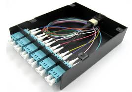
MPO/MTP cassette modules provide secure transition between MPO/MTP and LC or SC discrete connectors. They are used to interconnect MPO/MTP backbones with LC or SC patching. MPO/MTP Cassettes are designed to reduce installation time and cost for an optical network infrastructure in the premises environment. The modular system allows for rapid deployment of high density data center infrastructureCassette as well as improved troubleshooting and reconfiguration during moves, adds and changes. Except for that, it has other advantages reflected in these sides:
  • MPO/MTP interface–MPO/MTP components feature superior optical and mechanical properties.
  • Optimized performance–Low insertion losses and power penalties in tight power budget, high-speed network environments.
  • High density–12 or 24 fiber cassettes can be mounted in 1U scaling up to 72 or in 3U scaling up to 336 discrete LC connectors.
The above shows that the MPO/MTP system is a good solution for data center requirements. This high density, scalable system is designed to enable thousands of connections. Fiberstore offers a wide range of MPO/MTP trunk cables, harness cables and cassettes (or patch panels).
Originally published at http://www.china-cable-suppliers.com/mpomtp-solutions-for-high-density-applications.html

2015年10月13日星期二

How to Reduce the FTTx Roll-Out Cost?

With the increasing challenge to provide higher levels of broadband access to more demanding customers, the management of the physical network infrastructure, fiber to the x (FTTx), to enable new services is an increasingly critical part of the telecommunication operational landscape. FTTx is a collective term for various optical fiber delivery topologies that are categorized according to where the fiber terminates, including FTTN (fiber to the node or fiber to the neighbourhood), FTTC (fiber to the curb or fiber to the cabinet), FTTH (fiber to the home), etc.
Since the demand for the higher broadband is becoming eager, many countries are rolling out FTTx networks at even faster rates. As a result, there is an critical requirement to support quick, cost effective design and build of FTTx networks. According to some experienced network operators, there are some methods to reduce the FTTx roll out cost introduced below.
First and foremost, before you roll out FTTx network, you must take time to do a research that whether others has a more cost-effective way to do it. If yes, you can learn from others so that you will save a lot of energy and money. Then you should make a solid plan and ensure the procurement well-prepared. Last, you can validate your plan and stick to it after making sure that everything is in control.
When you get down to deploy your FTTx network, you can take these advice that may help you to reduce the cost.
Reuse existing duct infrastructure - The cost of civil works, such as trenching, has taken up over half of the whole cost. Thus, reusing existing ducts to avoid the need to dig trenches will save you a sum of money. In some countries, i.e, France and Spain, their operators has saved billions of Euros on installation costs by installing new cables on top of the existing utility and communication cables/conduits.
Use good design and documentation software with quality control - Since not all contractors are reliable, when you first deploy your network, you must use the devices with good quality. Only you invest a few more dollars to have it done right first time that you can reuse your expensive infrastructure again. If not, you will spend a lot more later on.
Do impact studies on the actual deployment area - The place where you are installing your network must be surveyed detailed in that it will blow up your deployment budget if you miss it. There are some factors you must take into consideration: uried utility densities, aerial routing legalities, geological soil and root systems and facilities locations.
Co-ordinate and automate roll out processes and project resources - To ensure that all workers are in good state and the work is efficient is a challenge for the daily operation. That is why we need to co-ordinate and automate roll out processes and project resources. Integrating the project team and subcontractor field resources into a single common information system would be good to the individual users to access to the areas that are appropriate to their role. This method can provide accurate, timely information to the central roll, leading to cost savings and increased customer satisfaction.
Maximize the end market as early as possible - The number of subscribers determines how much return you will get on your deployment investment. So make sure when trenching in paved streets to have ducts made up to every building’s property line, it is benefit for adding new subscribers. Try every effort to maximize the end market, and you will reduce your cost to the utmost extent.
When you deploy your FTTx network, you may need micro or ribbon cablesfusion splicers or something else. Remember that these devices must in good quality so that you can reuse again. In summary, If you follow the steps above, you will save a lot of money in deploying your FTTx network.
Originally published at http://www.chinacablesbuy.com/how-to-reduce-the-fttx-roll-out-cost.html

2015年10月7日星期三

Fiber Types and Associated Transceivers

An optical fiber is a flexible filament made by pure glass or plastic fiber used to transmit the light. There are two types of fiber: single mode fiber (SMF) and multimode fiber (MMF). Each kind of fiber includes several categories. Different category supports different transmission speeds and wavelengths. So there must be suitable optical transceivers connecting with related fibers for the network applications. The article tells about some categories of SMF and MMF and the associated interface type of transceivers.
Types of SMF and Associated Transceivers
The common SMF is defined in ITU G.652 standard. ITU G.652 is non-dispersion-shifted single mode fiber (NDSF). This fiber is optimized in 1310nm range. In order to eliminate the problems encountered by transmissions in the third window, other fiber types were developed. Dispersion-shifted fibers (DSF) with a zero dispersion at 1550 nm were defined in ITU G.653. Thus, attenuation is minimized so that longer distance cables are possible. However, even though this fiber type eliminates the problem for transmissions of single wavelengths at 1550 nm, it is not suitable for wavelength multiplexing applications as WDM transmissions can be affected by another non-linear effect called four-wave mixing. This brought non-zero dispersion shifted fibers (NZDSF) in the ITU G.655 standard. For this fiber type, the zero dispersion is shifted just outside the C-Band, usually around 1510 nm. This helps limiting the chromatic dispersion as the zero dispersion remains close enough to the transmission band.
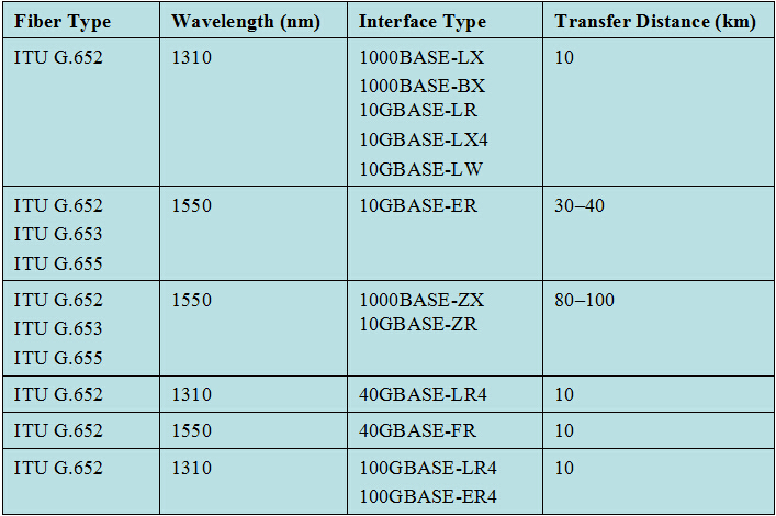
For SMF applications, there are various of transceivers to be used. These transceiver interfaces are defined by IEEE 802.3. They are used to transmit at 1310nm (ITU G.652) and 1550nm (like ITU G.653) wavelengths for long-haul transmission applications. The following figure shows us the different single mode fibers and associated interface types of transceivers.
Figure1. SMF/Interface Type
Single Mode Fibers & Interface Type
Types of MMF and Associated Transceivers
MMFs are described in ISO 11801 standard – OM1, OM2, and OM3 – which is based on the modal bandwidth of the MMF. OM4 was finalized in August 2009, and was published by the end of 2009 by the TIA. The letters "OM" stand for optical multi-mode. OM1 has a core size of 62.5 nm. It is most commonly used for 100 Megabit Ethernet applications. OM2 has a core size of 50 nm. It supports 10 Gigabit Ethernet at lengths up to 82 meters. OM3 also has a core size of 50 nm. It supports 10 Gigabit Ethernet at lengths up to 300 meters. Besides OM3 is able to support 40 Gigabit and 100 Gigabit Ethernet up to 100 meters. OM4 uses a 50nm core but it supports 10 Gigabit Ethernet at lengths up to 550 meters and it supports 100 Gigabit Ethernet at lengths up to 150 meters.
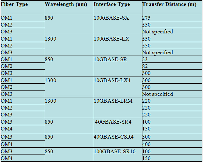
Like SMF, there are also corresponding transceivers applied with MMF. The differences are wavelength and transfer distance. For MMF is suitable for short distance transmission at the wavelengths of 850 nm and 1300 nm. Figure 2 shows the different types of MMF and associated interface type of transceivers.
Figure 2. MMF/Interface Type
Multimode Fibers & Interface Type
Fiberstore offers a full line of single mode and multimode fiber cables for all network applications. There are also a wide range of optical transceivers, such as SFP, SFP+, XFP, 40G QSFP and PON transceiver. All the transceivers can be connected with either SMF or MMF. And you can have the flexibility to custom the cables and transceivers to fit your specific requirements.
Originally published at http://www.china-cable-suppliers.com/fiber-types-and-associated-transceivers.html

2015年9月29日星期二

Basic Knowledge About Media Converter

Over the years, there has been a growing popularity of Ethernet networks, resulting in the increasing use of Ethernet switches in the network infrastructure. But there is problem that the majority of Ethernet switches on the market today are available only with either 10Base-T or 100Base-TX interfaces (i.e., RJ-45). And on the other hand, in order to meet the needs of longer distance transmission and immunity to electrical interference or eavesdropping/interception, fiber cable has been used on a large scale. Since the entire network is not all twisted pair, the problem of how to interconnect disparate cabling types to the switch must be solved. As a result, media converter, a device which can convert RJ-45 to one of the fiber types in use, has been designed.
What is a Media Converter?
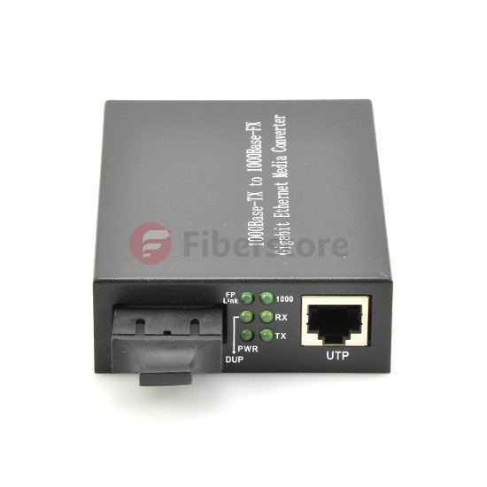
Media converter is a simple networking device that enables you to interconnect networks or network devices with different speeds, operation types, modes and media types. And the most common type usually works as a transceiver, converting the electrical signals in copper unshielded twisted pair (UTP) network cabling to light waves used for fiber optic cabling. It is essential to have the fiber optic connectivity if the distance between two network devices is greater than the copper cabling's transmission distance. Since media converters are IEEE compliant devices, they implement IEEE data encoding rules and Link Integrity Test.
Media Converter
Types of Media Converter
Generally, there are two types of media converter. One type is copper to fiber media converter, another is fiber to fiber media converter. And the illustration of each type will be given as follows.
Copper to fiber media converter - It is a compact device that provides seamless integration of copper and fiber cabling in Enterprise, Government and Service Provider networks. Also, it can be divided into two types, too. They are Ethernet copper to fiber media converter and TDM copper to fiber media converter. Ethernet copper-to-fiber media converter provides connectivity for Ethernet, Fast Ethernet, Gigabit and 10 Gigabit Ethernet devices. Some of it support 10/100 or 10/100/1000 rate switching, enabling the integration of equipment of different data rates and interface types into one seamless network.
As to TDM copper to fiber media converter, the common used types are T1/E1 and T3/E3 converters, providing a reliable and cost-effective method to extend traditional TDM (Time Division Multiplexing) telecom protocols copper connections using fiber optic cabling.
Fiber to fiber media converter - This media converter type can provide connectivity between multimode and single-mode fiber, or between dual fiber and single-fiber. What is more, it can support conversion from one wavelength to another. Fiber to fiber media converter is normally protocol independent and available for Ethernet, and TDM applications.
Benefits of Media Converter
Nowadays, media converter plays an important role in multi-protocol and mixed-media networks. In general, media conversion can deliver the following benefits for your network environment:
Cost Reduction - Compared with the hybrid media switches, the cost of media converters with cost-effective Ethernet switches is much lower. What is more, the two devices can do the same job. This type of media converter solution can cost significantly less than that relies on higher-layer devices such as routers or switches.
Flexibility and Simplification - It is of much flexibility for media converter to combine copper with 850 nm and 1300 nm multimode fiber and 1310 nm and 1550 nm single-mode fiber. In addition, With protocol transparency, it can be applied in anywhere in the local network or remote network whether it's a LAN or the WAN environment.
Ease of Use and High Availability - Configuring and installing redundant solution of media converter is much easier to handle and to manage than higher-layer devices. And it will makes the troubleshooting easier if you add management functions to the media converter.
Since media converter has so many advantages, it can support advanced bridge features – including VLAN, Quality of Service prioritization, Port Access Control and Bandwidth Control – that facilitate the deployment of new data, voice and video to end users. In a word, media converter does more than convert copper-to-fiber and convert between different fiber types. It can also provide all these sophisticated switch capabilities in a small, cost-effective device.
Originally published at http://www.chinacablesbuy.com/basic-knowledge-about-media-converter.html

2015年9月25日星期五

Guide to Cat5 Cable

UTP is short for "unshielded twisted pair". It's a kind of cable types with one or more pairs of twisted insulated copper conductors contained in a single sheath. UTP cables contain several different categories such as Category 3, Category 4, and Category 5. The word "Category" is abbreviated to "Cat". So Category 3 cable is Cat3 cable and Category 5 cable is Cat5 cable. They are different in the electrical performance criteria. Cat5 cable is the most popular UTP in the today’s computer networking. This article will introduce Cat5 cable.
Structure & Features
Inside Cat5 cable, there are 4 wire pairs. The four wire pairs are distinguished by the color of the insulation. The four colors are orange, green, blue and brown. Each pair has a common theme. One wire in the pair is a solid or primarily solid colored wire and the other is a primarily white wire with a colored stripe. For example, orange is for the solid colored wire and White/Orange for the striped cable. The color code shall be as follows:


e 4 wire pairs of Cat5 cable are carefully twisted. The twists of Cat5 are extremely important. The tighter the twists, the greater the signal integrity. With tighter twists, interference received by the cable is more likely to affect both wires in a pair equally, resulting in no change in the difference between them. This keeps greater data capacity over long distances. Besides, the tighter twists also suppress noise created by the cable because the magnetic field from one wire is canceled by the other, making it less prone to interfering with other cables.
Cat5 cable
Advantages and Disadvantages
Most computer users tend to choose Cat5 cable for their network. That’s because Cat5 cable is cheap. It’s also ideal for a variety of applications, such as computer networks and telephone wiring. And it can reach high-transfer rates. Cat5 cable provides performance of up to 100 MHz and is suitable for 10BASE-T and 100BASE-TX (Fast Ethernet). However, Cat5 cable gradually looses its advantage in the constantly advancing environment of technology. The data transfer through Cat5 cable is limited. It can only handle 100 M per second, and thus is not as effective for larger corporate networks or for any process that requires large data streams such as in modern television transfers.
Comparison with Other UTPs
To meet the high bandwidth needs, Cat5E, Cat6, Cat7 are recommended to the market. Cat5E is an enhanced version of Cat5 to support Gigabit speed which is ten times faster than Fast Ethernet. Cat6 cable is the next step of Cat5E. Compared with Cat5 cables, Cat6 provides lower crosstalk, a higher signal-to-noise ratio, and is suitable for 10GBASE-T (10-Gigabit Ethernet). Cat7 cable is backwards compatible with Cat5 and Cat6 Ethernet. Cat7 has more strict specifications for crosstalk and system noise than Cats. As time goes on, Cat8 cable is provided in the market to satisfy the 40G Ethernet (40GBASE-T).
From the above, with low cost and multiple applications advantages, Cat5 once has been the most common UTP. As higher bandwidth is needed, people tend to other UTPs such as Cat5E, Cat6, Cat7 and CAT8. So guess what kind of twisted pair cabling will appear next? The enhanced Cat8? Or Cat9? There is no exact answer. But the certainty is that the research on cabling work will never stop. And there will be optimized cables to meet the high bandwidth requirements.
Originally published at http://www.china-cable-suppliers.com/guide-to-cat5-cable.html

2015年9月18日星期五

Why the Future of Active Optical Cable Is Bright?

Driven by the demand for more bandwidth for data center, networking is challenging interconnect technologies like Ethernet, Infiniband, Fibre Channel, and Serial-Attached SCST (SAS). Transceivers such as SFP+, QSFP+ or CXP can accept a passive copper-based cable for lengths of 5-7 meters or an actively copper-based cable for lengths up to 15 meters. To seek lower cost, lower power consumption and lower link latency over longer distances, active optical cable (AOC) emerged.
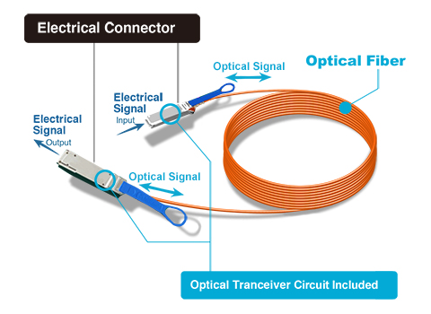
AOC is a cabling technology that accepts the same electrical inputs as a traditional cooper cable. But it uses optical fiber to joint the connectors terminated on each end of the cable. AOC uses electrical-optical conversion on the cable ends to improve speed and data transmission distance of the cable not sacrificing compatibility with standard electrical interfaces.
Active-Optical-Cable
Nowadays, the AOC market is fast growing. How does this happen? Then the following will tell a few advantages of AOC by comparing it with copper cable and optical transceiver.
Compared With Copper Cable

  • Lighter weight 
    Compared with copper cable which has existed in the market for decades, AOC is lighter. For example, five meters of copper cable weighs about one kilogram. Ten meters of AOC weighs less than 150g. The weight difference is obvious. Thus, AOC has fewer chances of damage to switch ports. The lighter and thinner optical cables are easy to manage and maintain and requires less space. Besides, it allows better airflow for cooling and has lower power consumption.
  • Longer Distance 
    The other key characteristics of AOC is active. That’s also the big difference from copper cable. Passive copper will suffer excessive bit error rates when the distance is beyond five meters. AOC is in bit error rates over distance. And it can operate reliably over the distance up to 100 meters. Some AOC products can even extend the reach to 1 km.
Compared With Optical Transceiver

As the name implies, AOC comes with optical connectors on each end that provide electrical-optical conversion and optical transmission. So users can remove the pluggable copper-based transmission device (usually either a CX-4 or QSFP) and plug in the active cables transceiver/connector, whose form factor mirrors that of the copper device it replaces. Compared with the transceiver products, AOC can avoid some of the obstacles that fiber has encountered in data centers. What’s more, it has much greater simplicity and reliability, as it’s factory terminated. And there is no risk of mis-matching polarities, dirt entering the assemblies, or different manufacturers’ tolerance mismatching.
Because of these advantages, the demand for the AOC is increasing as an alternative to copper cable. Some vendors such as Fiberstore have rushed to develop products to meet this hot spot. Fiberstore keeps improving its product line of AOC in order to better satisfy the application of 10G, 40G to 100G Ethernet. At present, there are a variety of AOCs in the market, such as 10GbE SFP+ AOCs, 40Gbps QSFP+ AOCs and 120G CXP AOCs.
The market is expected to grow to just under $100 million and 450,000 units by 2015 according to some forecasts. The increasing growth in commercial data centers and the advent of high speed transmission will make AOCs achieve sales of around US $1 billion by 2018 that means the future of AOCs is bright.
Originally published at http://www.china-cable-suppliers.com/why-the-future-of-active-optical-cable-is-bright.html