2015年8月27日星期四

Are You Familiar with Fiber Optic Coupler?

Optical coupler is the extremely important component in a number of phonics devices and systems that couple or split light through wave-guides or fibers. Fiber optic couplers can be either active or passive devices. The difference between active and passive couplers is that a passive coupler redistributes the optical signal without optical-to-electrical conversion. Active couplers are electronic devices that split or combine the signal electrically and use fiber optic detectors and sources for input and output.
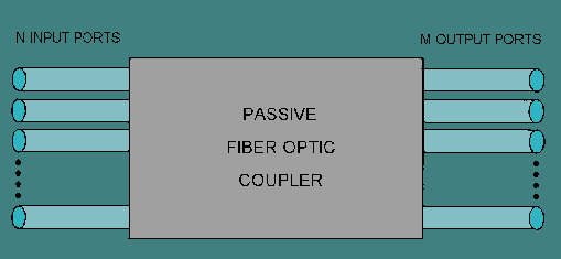
fiber optic coupler
A basic fiber optic coupler has N input ports and M output ports (showed in the above picture) which typically range from 1 to 64. But generally, they are four-port devices and their operation relies on the distributed coupling between two individual waveguides in close proximity, which results in a gradual power transfer between modes supported by the two waveguides. The brief principles of four-ports fiber optic coupler is given in the following picture. If light enters into the port 1, it will be splitted into the output ports between ports 3 and 4. And port 2 functions in the same way. And sometimes, one of port 1 or port 2 is unused, so the fiber optic coupler will act as a Y or T coupler (Y or T stands for the form of transmission route).
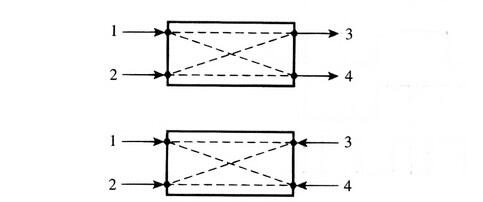
brief principles of four-ports fiber optic coupler
As we have known before, fiber optic coupler can couple or split light, so it also can be called fiber optic splitter. In fact, splitter is named for the function of the device, coulper named for its working principle. These days, the most popular types are fused fiber optic couplers and planar lightwave circuit (PLC) splitter.
Fused fiber optic coupler is a kind of fiber optic couplers, which is formed based on fused biconical taper (FBT) technology. Therefore, it is also known as FBT coupler. It can work on three different operating bands such as 850nm, 1310 nm and 1550nm.
Planar Lightwave Circuit (PLC) Splitter is designed to manage the power of optical signals through splitting and routing. It can provide reliable light distribution and is based on planar lightwave circuit technology. Compared with FBT fused coupler of lower cost, PLC splitter has wider operating wavelength range which is from 1260 nm to 1620 nm, and wider temperature range from -40ºC to +85ºC, better uniformity, higher reliability and smaller size.
Currently, fiber optic coupler is widely used in that it can support FTTX (FTTP, FTTH, FTTN, FTTC), passive optical networks (PON), local area networks (LAN), CATV systems, amplifying, monitoring system and test equipment. As a result, fiber optic coupler with good quality is required. Fiberstore can offer you various kinds of fiber optic couplers with good quality, including fused fiber optic coupler and Planar Lightwave Circuit (PLC) Splitter. For more information, you can visit Fiberstore.
Originally published at http://www.chinacablesbuy.com/category/fiber-optic-network
2015年8月24日星期一

PON - a Better Network Solution

When choosing a best fiber architecture for the network, many planners may choose PON today. PON, short for passive optical networks, is a telecommunication network that uses point-to-multipoint fiber to the end-points in which unpowered optical splitters are used to enable a single optical fiber to serve multiple end-points. "Passive" means optical transmission has no power requirements or active electronic parts when the signal is going through the network. It is the core underpinning of fiber optical service.
Introduction of PON
Passive optical network is widely applied in fiber-to-the-curb (FTTC), fiber-to-the-building (FTTB), or fiber-to-the-home (FTTH), which is decided by the places it terminates. Commonly, it is made up of an optical line terminal (OLT) in the central office and a number of optical network units (ONU) near end users. From the picture below, we can get a brief understanding of the working process of it.
First and foremost, the data or the signals in the central office will be transmitted over a single optical fiber without interfered by each other, because encryption can prevent eavesdropping. And then the passive splitter will separate the signals into several optical network units which can be up to 64 units.
PON
Classifications of PON
The first PON systems which is based on Asynchronous Transfer Mode (ATM, or "cell switching") were called "APON". It has been achieved significant commercial deployment and still be applied in someplace today. The "Broadband PON" comes after APON. Typically, these two systems both have downstream capacity of 155 Mbps or 622 Mbps and upstream capacity of 155 Mbps.
And as the technology advanced, there is a growing requirements of higher capacity. As a result, APON and BPON is gradually replaced by GPON. GPON, short for Gigabit-capable passive optical network, is the successor of APON and BPON, and also based on ATM transport. Typically, its capacity of upstream ranges from 622 Mbps to 1.25 Gbps, while the downstream capacity ranges from 622 Mbps to 2.5 Gbps. In today's fiber-to-the-home (FTTH) networks, GPON is most widely deployed, which is generally considered suitable for consumer broadband services for the next 5 to 10 years.
EPON (Ethernet passive optical network) is the rival of GPON, using Ethernet packets instead of ATM cells. It is cheaper to deploy than GPON, but it has not garnered the level of acceptance of GPON.
And WDM PON (wavelength-division multiplexing passive optical network) is a network that combines WDM technology with PON system. It can use wavelength-division multiplexing to split each signal into different branches.
Advantages of PON
Compared with the traditional enterprise network, PON network is obvious superior to it. And there are several advantages of PON.
Energy savings – PON system does not need rack mount switches and other active devices in remote locations so that it can reduce a number of heat generating devices that must be cooled and powered, thereby generating energy savings. Also, there are reduced HVAC (Heating Ventilation Air Conditioning) requirements, since there is no radiant heat with fiber cabling.
Lower cost – Due to lower power consumption, reduction in floor space, and yearly reduced maintenance costs, the enterprise will realize significant operational expense savings over the life of the system of 45-70% over that of a traditional copper based system, as well.
Optimized bandwidth utilization – with dynamic allocation of bandwidth, the system can provide optimized network connectivity to those application and users requiring the greatest bandwidth, while facilitating future proofing.
Now, the Ethernet market becomes more and more popular, so PON is gradually getting into a bright future. With these significant advantages, PON can meet the changing demands of the enterprise network more quickly and easily. And at present, the most popular network systems are GPON and EPON. Fiberstore offers various PON products, including optical line terminals and optical network units, and if you want to deploy your network most efficiently, Fiberstore is your best choice.

2015年8月20日星期四

Introduction of Singlemode Fiber Patch Cable

When signals are transmitted over a long distance, singlemode fiber patch cable which plays a vital part in the remote telecommunication should not be ignored. Singlemode fiber patch cable is a single strand (most applications use 2 fibers) of glass fiber with a diameter of 8.3 to 10 microns, which only transmits single mode on a given operating wavelength. The dispersion in it is little, so that singlemode fiber cable can support Gigabit Ethernet data transfer up to 10 kilometers in distance.
Comparison With Multimode Fiber Patch Cable
Singlemode fiber patch cable which we talked before is one type of fiber patch cable, and another type is multimode fiber patch cable. Different from singlemode fiber patch cable, multimode fiber patch cable can transmit multimode on a given operating wavelength. But what is the main difference between them? And how can we tell them apart?
The main difference between them is the size of their respective cores. Singlemode fiber has a smaller core than multimode’s. As we said before, the diameter of its core is about 8.3 to 10 microns, while the core of multimode fiber is about 50, 62.5 mm or even higher. As a result, the larger core gathers more light in multimode fiber patch cables than singlemode cables, and this light reflects off the core and allows more signals to be transmitted. In a word, the size of the cores determine their nature.
Another difference is the transmission distance. Due to the smaller core, singlemode fiber patch cable has less signal attenuation than multimode fiber patch cable, so that it can be applied for long distance transmission. On the other hand, although multimode fiber patch cable can transmit multimode, the dispersion between modes is large, which would be a limitation for transmission frequency of digital signals. Therefore, multimode fiber patch cable is usually used for short distance transmission.
Types of Singlemode Fiber Patch Cable
According to the different specification, singlemode fiber can be divided into different kinds. In the picture below, there are three specifications which defined the singlemode fiber. They are IEC (short for International Electrotechnical Commission), ITU (short for International Telecommunication Union) and TIA (short for Telecommunications Industry Association). You can have a visual description from this picture.
types of singlemode fiber
In order to help you to have a better understanding of the types of singlemode fiber, we will take G.652 for an example. G.652 covers singlemode NDSF (non-dispersion-shifted fiber), which has no attenuation coefficient in the 1310 nm range. And low water peak fiber has been specifically processed to reduce the water peak at 1400 nm to allow use in that range.
When put into practice, singlemode fiber cable is often connected with connectors to transmit data. For example, LC to ST fiber patch cable is a cable with LC connector on the one end and ST connector on the other end. Also, the connectors to connect the cables have various kinds, such as SC, FC, ect. And if you want to buy these cables with good quality, Fiberstore is a good choice.

2015年8月17日星期一

Why is Fiber Optic Cable a Better Choice Than Copper Cable?

Nowadays, you can see fiber optics is deployed in many industries, most notably in telecommunications and computer networks. As a result, fiber optic cable is widely used. On the contrast, the utilization of copper cable declines. And as the construction of fiber optics develops further, some entrepreneurs even announced that fiber optic cable will replace copper cables. In spite that these words are not authoritative and unbelievable, we still can see the prospect of fiber optic cable is excellent. So here comes the question: Why is fiber optic cable a better choice than copper cable?
What Are Fiber Optic Cable and Copper Cable?
Fiber optic cable is a cable containing one or more optical fibers that are used to carry light. (And it should be differentiated from fiber optic patch cord which consists of a short length of optical fiber with a connector on both ends. For example, LC fiber optic cable, one kind of fiber optic patch cord, consists of optical fiber with a connector whose type is LC.) Commonly, fiber optic cable can be divided into single-mode fiber and multi-mode fiber. Single-mode fiber cable sends signals with laser light, while multi-mode fiber sends signals with light-emitting diodes or LEDs. The thickness and diameter of multi-mode cable are bigger than the single-mode cable’s.
Copper cable is a cable made by copper medium. In copper networks, copper cable is the key component which can be divided into three sub-types: unshielded twisted pair (UTP), screened twisted pair (F/UTP) and shielded twisted pair (S/FTP). And the main medium of signal transmission in copper cable is twisted pair.
Advantages of Fiber Optic Cable Over Copper Cable
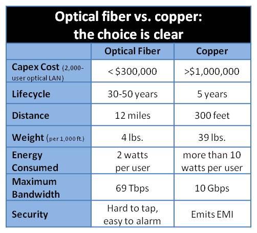
There are some aspects that can show fiber optic cable is a better choice than copper cable. And in order to give you a visual description, here is a table below of the comparison of fiber optic cable and copper cable so that you can know it clearly. Also, we will talk about some relative importance of these points in detail.
optical cable vs. copper cable
Higher carrying capacity and wider transmission band: Optical fibers are thinner than copper wires, so more fibers can be bundled into a given-diameter cable than copper wires, allowing more phone lines to go over the same cable or more channels to come through the cable into your business or home. The bandwidth of fiber optics can be up to 50000GHz. For instance, optical fiber system with speed of 2.4Gb/s can transmit more than 3000 phone lines at the same time.
Less signal degradation: The loss of signal in optical fiber is less than in copper wire. Recently, the attenuation of optical fiber is declined to 0.2dB/KM. Therefore, the distance of signal transmission can be longer, even more than a few hundred kilometers because of less attenuation. And also, because the signals degrade less, it can use low power transmitter to transmit signals instead of the high-voltage electrical transmitters needed for copper wires so that it can save some cost.
Light signals: In fiber optic cables, light signals from one fiber do not interfere with those of other fibers in the same cable, which is greatly different from the electric signals in copper cables. This feature means there would be a clearer phone conversation or TV reception using fiber optic cables.
At present, there is point we should admit that copper cable shares most parts of the market. But with so many advantages over copper cable, we strongly believe that fiber optic cable will have a bright future.

2015年8月13日星期四

Guide to Optical Amplifier

In pursuit of high transmission capacity, people have been tried many ways. For example, they pave more cables or use the TDM (time domain multiplexer) to improve the transmission capacity. But in these traditional ways, signals could become weaker in power through the fiber link. And the further they are transmitted, the weaker the signals will be until they can not be detected. With the advanced of technology, optical amplifier which is a better solution to improve the transmission capacity came around. It can strengthen the attenuated signals and even can bring them back to the original level. And now it is mainly applied in DWDM technology so that DWDM technology can support long-haul transmission.
Working Principles of Optical Amplifier
Optical amplifier is a device that can amplifier optical signals directly, which does not need to convert optical signals to electric signals first. And we will take the common kind for example to explain its working principles, namely, EDFA (erbium doped fiber amplifier). Optical fiber is often doped with rare-earth elements, such as erbium or praseodymium which can be pumped into a excited state by pump laser. When input signals pass by the fiber, they will stimulate the excited atoms of erbium so that the atoms of erbium can release their energy in the form of emitted light photons. It is the emitted light photons who has the same phase and wavelength with input signals that amplify the optical signals.
Working Principles of EDFA
Working Principles of EDFA
Types of Optical Amplifier
Optical amplifier can be divided into three types now. They are the doped fiber amplifier, the semiconductor optical amplifier and the Raman amplifier. Next we will introduce each of amplifiers.
Doped fiber amplifier has several types according to the kinds of rare earth elements. Erbium-doped fiber amplifier is the most common one. Just like we said before, its amplifying medium is the fiber doped with erbium elements. The amplified light’s wavelength is around 1550 nm, which suffers minimum attenuation. And this amplifier has low noise and is applied in the long-haul telecommunication networks. The second is semiconductor optical amplifier whose gain medium is undoped InGaAsP. Compared with EDFA, it is less expensive and more suitable for local networks. Raman amplifier’s gain medium is undoped optical fiber. It is made with Raman scattering effect which is an important non-linear effect. By the early part of 2000s, it is used for long-haul (typically between 300 and 800 km) or ultra-long-haul (typically longer than 800 km) fiber-optics transmission system. And this amplifier has been commercialized these days, with sold at a high price.
The advent of optical amplifier is a great success in optical fiber communication technology. At present, it has been become a basic device in modern telecommunication networks and brings much effectiveness to economy and society, which presents a good trend for the market prospect.

2015年8月10日星期一

What Is CWDM?

As we all known, WDM (wavelength division multiplexing) is a technology that can transmit multiple different wavelength lasers on a single optical fiber, and widely used in optical networks. CWDM (coarse wavelength division multiplexing), as one type of WDM technology, first came in the 1980s, mainly being used to transmit digital video signal in the multimode fiber. However, it did not interested telecommunication service providers much until now. In recent years, with the development of metropolitan area network which has short transmission distance and do not need optical amplifier, there is a growing technology investment for it because it is a cost-effective solution for telecommunication service providers. We could say this is the time that CWDM exists with great significance.
Introduction of CWDM
As we said above, CWDM is one type of WDM technology, oriented to metropolitan area network. According to ITU-T G.694.2 standard, it has three wavelength bands: O band, E band and S+C+L band. The wavelength of O band is about 1270 nm, 1290 nm, 1310 nm, 1330 nm and 1350 nm. The wavelength of E band is about 1370 nm, 1390 nm, 1410 nm, 1430 nm and 1450 nm. As to S+C+L band, the wavelength is about 1470 nm, 1490 nm , 1510 nm, 1530 nm, 1550 nm, 1570 nm, 1590 nm and 1610 nm. And the channel spacing in CWDM system is typically 20 nm as the picture shows below. So the number of its channels on the same link can be up to 18. And due to its wide channel spacing the temperature control could not be so rigid. Typically, its operating temperature is from 0 to 70°C. And the use of uncooled lasers brings a low cost.
Typical transmittance for coarse wavelength multiplexer
Advantages of CWDM
One of the biggest advantage of CWDM is low cost. As we have mentioned before, CWDM with the wider channel spacing do not need rigid temperature stability control, so the construction of laser device could be simplified. This feature of it is of great help to reduce the cost.
Another advantage of CWDM is that it has small volume and low power consumption. The laser in CWDM system do not need semiconductor cooler and temperature controlling, so it can reduce the power consumption obviously. Its power consumption is only 0.5 W. And the laser module which is simplified in CWDM system can make the volume of optical transceiver module reduced so that it can save a lot of room space.
Application of CWDM
With these advantages, CWDM technology is applied in various areas now, such as enterprise LAN and SAN connection, central office to customer premise interconnection and so on. And one of the most commonly devices is CWDM SFP. CWDM SFP is the transceiver which made by CWDM technology. It is of great simplicity, flexibility and interoperability. Mostly there are eight center wavelengths available from 1470nm to 1610nm, with each step 20 nm. Of course, there are some other CWDM devices,too. But today we are not going to list the products.
In a word, because of its good capacity and low cost, CWDM provides a better solution for metropolitan area network. I believe it will be a hot spot in metropolitan area network construction in the next few years.

2015年8月4日星期二

How Much Do You Know About 40G Transceiver?

40 Gigabit Ethernet, as the computer networks technology, is mainly used to transmit Ethernet frames at rates of 40 gigabit per second. Now it has become a broad selection of vendors because it is cost-effective and reliable. 40G optical transceiver that is used to plug into network servers and a variety of components including interface cards and switches can be applied in 40 Gigabit Ethernet. It is made up of independent optical transmit and receive channels, and its rate is up to 5 Gb/s.
Recently, 40G transceiver can be divided into different types by different standards. According to its standard form factors, there are some common types: CFP transceiver, CXP transceiver and QSFP transceiver, ect. CFP (C form-factor pluggable) transceiver, with 12 transmit and 12 receive 10-Gbps lanes, can support three 40 Gigabit Ethernet ports. The first generation of CFP, which is of bigger size, is more suitable for singlemode optical fiber cable, and also can match multimode fiber or copper cable. CXP transceiver, whose size is smaller than CFP, can provide 12 channels in each direction as well. It is suitable for multimode optical fiber cable and copper cable. The size of QSFP (quad small pluggable) is similar with CXP. It can provide four transmission channels and receive channels, supporting multimode optical fiber cable and copper cable in 40G Ethernet. In the future, it may support singlemode optical fiber cable.
According to the the definition of Physical Layer Specifications, the interface of it, which is used to connect with the ports of switches, can be divided into various kinds, such as 40GBASE-CR4, 40GBASE-KR4, 40GBASE-SR4,40GBASE-LR4 and so on. The main difference between them lies in the kind of cable they operate on. 40GBASE-CR4 is a port type for twin-ax copper cable. 40GBASE-KR4 is a port type for backplanes. 40GBASE-SR4 (short range) is a port type for multimode fiber and uses 850 nm lasers. 40GBASE-LR4 (long range) is a port type for singlemode fiber and uses 1300 nm lasers. And also, the difference types determine them to be applied in different situations. Taking the 40GBASE-SR4 transceiver and 40GBASE-LR4 transceiver for example, 40GBASE-SR4 transceiver is used to transmit in short distance while 40GBASE-LR4 transceiver is designed for long-hual transmission.
40G transceiver
Nowadays, 40G transceiver is s now be widely used in the high performance computing, cloud computing industry, high-density data exchange center and so on. But why there are so many customers choosing it? Besides its comprehensive application and flexible design, the most important factor is the user’s network of actual business requirements. From the market we can see that, as its capability is much better than 10G transceiver and the cost is lower than 100G transceiver, 40G transceiver is the best choice to meet their needs.
As technology advanced, 40G transceiver will be developed further. Faced with the development of 40G optical transceiver modules, Fiberstore produces and sells 40G transceiver with high quality and at reasonable price. If you need 40G fiber optical transceivers, Fiberstore will be your first choice.