2015年10月26日星期一

Differences Between FBT Splitter and PLC Splitter

Nowadays, with the further popularization of the optical fiber communication, fiber optic splitter plays an increasing significant role in many of today’s optical network topologies. Although there are variations of splitter types, the two most commonly deployed splitters are FBT (Fused Biconical Taper) splitter and PLC (Planar Lightwave Circuit) splitter. So, when you deploy your network, what kind of splitter you should choose may be a problem for you. And in order to solve this problem, this paper will give you a detailed introduction of differences between FBT splitter and PLC splitter.
Definition of FBT Splitter and PLC Splitter
Before you get to know the features of them, first you should know what them are. Next, each splitter will be introduced.
FBT Splitter - FBT is a traditional technology that two fibers are typically twisted and fused together while the assembly is being elongated and tapered. The fused fibers are protected by a glass substrate and then protected by a stainless steel tube, typically 3mm diameter by 54mm long. FBT splitters are widely accepted and used in passive optical networks, especially for instances where the split configuration is not more than 1x4. The slight drawback of this technology is when larger split configurations such as 1x16, 1x32 and 1x64 are needed.
PLC splitter - A PLC splitter is a micro-optical component based on planar lightwave circuit technology and provides a low cost light distribution solution with small form factor and high reliability. It is manufactured using silica glass waveguide circuits that are aligned with a V-groove fiber array chip that uses ribbon fiber. Once everything is aligned and bonded, it is then packaged inside a miniature housing. PLC Splitter has high quality performance, such as low insertion loss, low PDL (Polarization Dependent Loss), high return loss and excellent uniformity over a wide wavelength range from 1260 nm to 1620 nm and have an operating temperature -40°C to +85°C.
Feature Comparison of FBT Splitter and PLC Splitter
In the past few years, splitter technology has made a huge step forward, especially the PLC splitter technology. This situation resulted in that PLC splitter has become a higher reliable type of device compared to the traditional FBT splitter. Although being similar in size and appearance, the internally technologies behind these types vary, thus giving service providers a possibility to choose a more appropriate solution.
Operating Wavelength - As is mentioned above, PLC splitter can provide a range of operating wavelength from 1260 nm to 1620 nm. But FBT splitters only support three wavelengths (850/1310/1550 nm) which makes these devices unable to operate on other wavelengths.
Operating Temperature - Commonly, FTB splitter is to a high extent temperature sensitive, providing a stable working range of -5 °C to 75 °C. While PLC splitter operates at wider temperature range (-40 °C to 85 °C), allowing its deploying in the areas of extreme climate.
Split Ratio - The split ratio of FBT splitter is 1:8 and it can be higher with higher failure rate. The split ratio of PLC splitter can go up to 64, which is equal to all branches, thus providing a high reliability.
Cost - FBT splitter is made out of materials that are easily available, for example steel, fiber, hot dorm and others. All of these materials are low-price, which determines the low cost of the device itself. PLC splitter manufacturing technology is more complex. It uses semiconductor technology (lithography, etching, developer technology) production, hence it is more difficult to manufacture. Therefore, the price of this device is higher.
FBT and PLC splitter feature comparison
Conclusion
In a word, Compared with FBT splitter, the capacity of PLC splitter is better, but costlier than the FBT splitter in the smaller ratios. You can choose it according to your requirements. Fiberstore offers both FBT splitter and PLC splitter with good quality and low price. Whether in FTTx systems or in traditional optic network, Fiberstore splitter can help you to maximize the functionality of optical network circuits.
Originally published at http://www.chinacablesbuy.com/differences-between-fbt-splitter-and-plc-splitter.html
2015年10月21日星期三

MPO/MTP Solutions for High Density Applications

As the bandwidth demands grow rapidly, data centers have to achieve ultra-high density in cabling to accommodate all connections. MPO/MTP technology with multi-fiber connectors offers ideal conditions for high-performance data networks in data centers. This article will introduce information about MPO/MTP solutions, such as MPO/MTP trunk cable, MPO/MTP harness cable and MPO/MTP cassettes.
MTP/MPO Trunk Cable
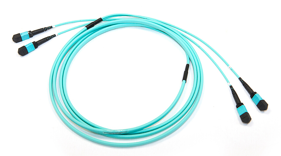
MTP/MPO trunk cables are terminated with the MTP/MPO connectors (as shown in the following figure). Trunk cables are available with 12, 24, 48 and 72 fibers. MTP/MPO trunk cables are designed for data center applications. The plug and play solutions uses micro core cable to maximize bend radius and minimize cable weight and size. Besides, MTP/MPO trunk cables also have the following advantages:
  • Saving installation time–With the special plug and play design, MTP/MPO trunk cables can be incorporated and immediately plugged in. It greatly helps reduce the installation time.
  • Decreasing cable volume–MTP/MPO trunk cables have very small diameters, which decrease the cable volume and improve the air-conditioning conditions in data centers.
  • High quality–MTP/MPO trunk cables are factory pre-terminated, tested and packed along with the test reports. These reports serve as long-term documentation and quality control.
Trunk-Cable
MPO/MTP Harness Cable
MPO/MTP harness cable (as shown in the following figure) is also called MPO/MTP breakout cable or MPO/MTP fan-out cable. This cable has a single MTP connector on one end that breaks out into 6 or 12 connectors (LC, SC, ST, etc.). It’s available in 4, 6, 8, or 12 fiber ribbon configurations with lengths about 10, 20, 30 meters and other customized lengths. MPO/MTP harness cable is designed for high density applications with required high performance. It’s good to optimize network performance. Other benefits are shown as below:
  • Saving space–The active equipment and backbone cable is good for saving space.
  • Easy deployment–Factory terminated system saves installation and network reconfiguration time.
  • Reliability–High standard components are used in the manufacturing process to guarantee the product quality.
Harness-Cable
MPO/MTP Cassette
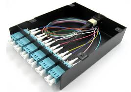
MPO/MTP cassette modules provide secure transition between MPO/MTP and LC or SC discrete connectors. They are used to interconnect MPO/MTP backbones with LC or SC patching. MPO/MTP Cassettes are designed to reduce installation time and cost for an optical network infrastructure in the premises environment. The modular system allows for rapid deployment of high density data center infrastructureCassette as well as improved troubleshooting and reconfiguration during moves, adds and changes. Except for that, it has other advantages reflected in these sides:
  • MPO/MTP interface–MPO/MTP components feature superior optical and mechanical properties.
  • Optimized performance–Low insertion losses and power penalties in tight power budget, high-speed network environments.
  • High density–12 or 24 fiber cassettes can be mounted in 1U scaling up to 72 or in 3U scaling up to 336 discrete LC connectors.
The above shows that the MPO/MTP system is a good solution for data center requirements. This high density, scalable system is designed to enable thousands of connections. Fiberstore offers a wide range of MPO/MTP trunk cables, harness cables and cassettes (or patch panels).
Originally published at http://www.china-cable-suppliers.com/mpomtp-solutions-for-high-density-applications.html

2015年10月13日星期二

How to Reduce the FTTx Roll-Out Cost?

With the increasing challenge to provide higher levels of broadband access to more demanding customers, the management of the physical network infrastructure, fiber to the x (FTTx), to enable new services is an increasingly critical part of the telecommunication operational landscape. FTTx is a collective term for various optical fiber delivery topologies that are categorized according to where the fiber terminates, including FTTN (fiber to the node or fiber to the neighbourhood), FTTC (fiber to the curb or fiber to the cabinet), FTTH (fiber to the home), etc.
Since the demand for the higher broadband is becoming eager, many countries are rolling out FTTx networks at even faster rates. As a result, there is an critical requirement to support quick, cost effective design and build of FTTx networks. According to some experienced network operators, there are some methods to reduce the FTTx roll out cost introduced below.
First and foremost, before you roll out FTTx network, you must take time to do a research that whether others has a more cost-effective way to do it. If yes, you can learn from others so that you will save a lot of energy and money. Then you should make a solid plan and ensure the procurement well-prepared. Last, you can validate your plan and stick to it after making sure that everything is in control.
When you get down to deploy your FTTx network, you can take these advice that may help you to reduce the cost.
Reuse existing duct infrastructure - The cost of civil works, such as trenching, has taken up over half of the whole cost. Thus, reusing existing ducts to avoid the need to dig trenches will save you a sum of money. In some countries, i.e, France and Spain, their operators has saved billions of Euros on installation costs by installing new cables on top of the existing utility and communication cables/conduits.
Use good design and documentation software with quality control - Since not all contractors are reliable, when you first deploy your network, you must use the devices with good quality. Only you invest a few more dollars to have it done right first time that you can reuse your expensive infrastructure again. If not, you will spend a lot more later on.
Do impact studies on the actual deployment area - The place where you are installing your network must be surveyed detailed in that it will blow up your deployment budget if you miss it. There are some factors you must take into consideration: uried utility densities, aerial routing legalities, geological soil and root systems and facilities locations.
Co-ordinate and automate roll out processes and project resources - To ensure that all workers are in good state and the work is efficient is a challenge for the daily operation. That is why we need to co-ordinate and automate roll out processes and project resources. Integrating the project team and subcontractor field resources into a single common information system would be good to the individual users to access to the areas that are appropriate to their role. This method can provide accurate, timely information to the central roll, leading to cost savings and increased customer satisfaction.
Maximize the end market as early as possible - The number of subscribers determines how much return you will get on your deployment investment. So make sure when trenching in paved streets to have ducts made up to every building’s property line, it is benefit for adding new subscribers. Try every effort to maximize the end market, and you will reduce your cost to the utmost extent.
When you deploy your FTTx network, you may need micro or ribbon cablesfusion splicers or something else. Remember that these devices must in good quality so that you can reuse again. In summary, If you follow the steps above, you will save a lot of money in deploying your FTTx network.
Originally published at http://www.chinacablesbuy.com/how-to-reduce-the-fttx-roll-out-cost.html

2015年10月7日星期三

Fiber Types and Associated Transceivers

An optical fiber is a flexible filament made by pure glass or plastic fiber used to transmit the light. There are two types of fiber: single mode fiber (SMF) and multimode fiber (MMF). Each kind of fiber includes several categories. Different category supports different transmission speeds and wavelengths. So there must be suitable optical transceivers connecting with related fibers for the network applications. The article tells about some categories of SMF and MMF and the associated interface type of transceivers.
Types of SMF and Associated Transceivers
The common SMF is defined in ITU G.652 standard. ITU G.652 is non-dispersion-shifted single mode fiber (NDSF). This fiber is optimized in 1310nm range. In order to eliminate the problems encountered by transmissions in the third window, other fiber types were developed. Dispersion-shifted fibers (DSF) with a zero dispersion at 1550 nm were defined in ITU G.653. Thus, attenuation is minimized so that longer distance cables are possible. However, even though this fiber type eliminates the problem for transmissions of single wavelengths at 1550 nm, it is not suitable for wavelength multiplexing applications as WDM transmissions can be affected by another non-linear effect called four-wave mixing. This brought non-zero dispersion shifted fibers (NZDSF) in the ITU G.655 standard. For this fiber type, the zero dispersion is shifted just outside the C-Band, usually around 1510 nm. This helps limiting the chromatic dispersion as the zero dispersion remains close enough to the transmission band.
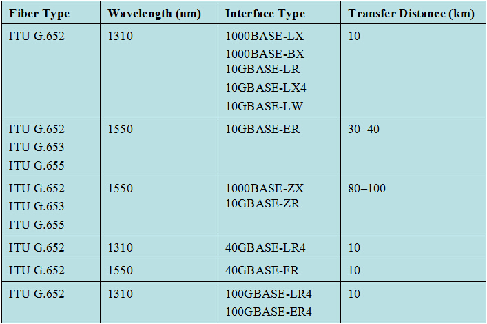
For SMF applications, there are various of transceivers to be used. These transceiver interfaces are defined by IEEE 802.3. They are used to transmit at 1310nm (ITU G.652) and 1550nm (like ITU G.653) wavelengths for long-haul transmission applications. The following figure shows us the different single mode fibers and associated interface types of transceivers.
Figure1. SMF/Interface Type
Single Mode Fibers & Interface Type
Types of MMF and Associated Transceivers
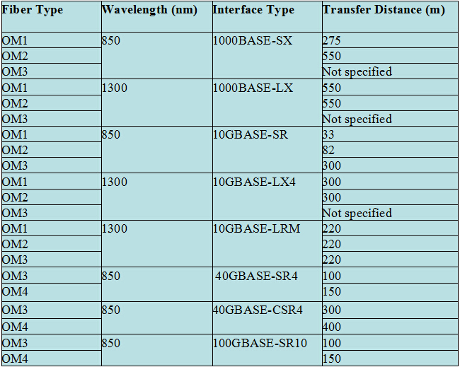
MMFs are described in ISO 11801 standard – OM1, OM2, and OM3 – which is based on the modal bandwidth of the MMF. OM4 was finalized in August 2009, and was published by the end of 2009 by the TIA. The letters "OM" stand for optical multi-mode. OM1 has a core size of 62.5 nm. It is most commonly used for 100 Megabit Ethernet applications. OM2 has a core size of 50 nm. It supports 10 Gigabit Ethernet at lengths up to 82 meters. OM3 also has a core size of 50 nm. It supports 10 Gigabit Ethernet at lengths up to 300 meters. Besides OM3 is able to support 40 Gigabit and 100 Gigabit Ethernet up to 100 meters. OM4 uses a 50nm core but it supports 10 Gigabit Ethernet at lengths up to 550 meters and it supports 100 Gigabit Ethernet at lengths up to 150 meters.
Like SMF, there are also corresponding transceivers applied with MMF. The differences are wavelength and transfer distance. For MMF is suitable for short distance transmission at the wavelengths of 850 nm and 1300 nm. Figure 2 shows the different types of MMF and associated interface type of transceivers.
Figure 2. MMF/Interface Type
Multimode Fibers & Interface Type
Fiberstore offers a full line of single mode and multimode fiber cables for all network applications. There are also a wide range of optical transceivers, such as SFP, SFP+, XFP, 40G QSFP and PON transceiver. All the transceivers can be connected with either SMF or MMF. And you can have the flexibility to custom the cables and transceivers to fit your specific requirements.
Originally published at http://www.china-cable-suppliers.com/fiber-types-and-associated-transceivers.html